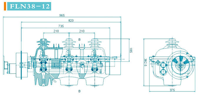
 FLN38-12 SF6 Load Break Switch
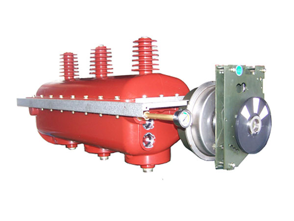 FLN38-24 SF6 Load Break Switch
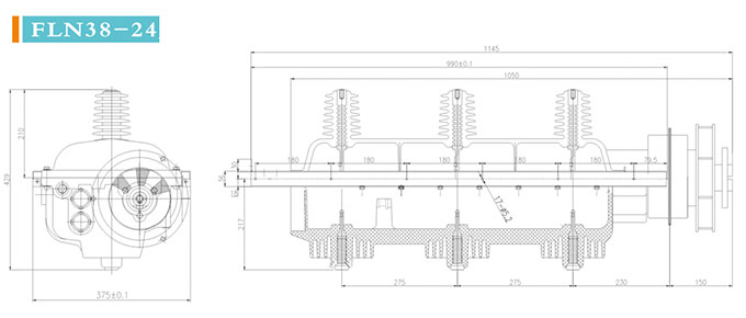
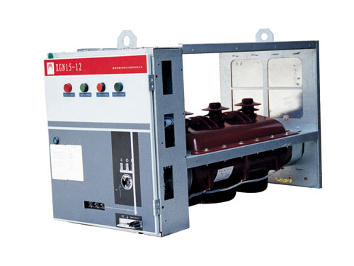

Introduction
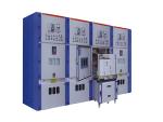
Economy, security and reliability come together in our FLN38-12/FLN38-24 SF6 load break switch, which is our newly developed disconnect switch that applies to XGN15 RMU. It comes with simple structure and reliable interlock, being easy for mounting and operating.
Structure
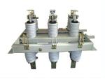
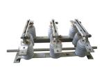
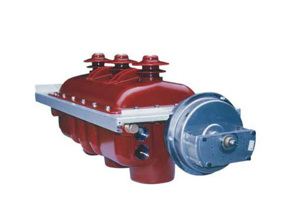
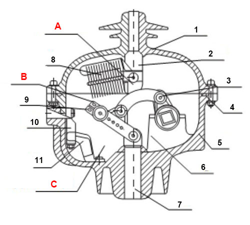
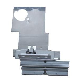
The SF6 gas insulated load break switch has the main circuit and the earthing circuit sealed in an epoxy resin based dielectric casing, which is excellent in insulating performance and contamination resistance. The casing is composed of the upper and lower insulating covers, cast together by APG technology. Its inner chamber is filled with SF6 gas in relative pressure of 0.4bar. The wall of the lower insulating cover is locally thinner, as a measure taken to prevent explosion. In case of accident, the over pressured SF6 gas can break through the explosion-proof channel and jet directly to the rear of the cabinet, release the pressure and ensure personal safety.
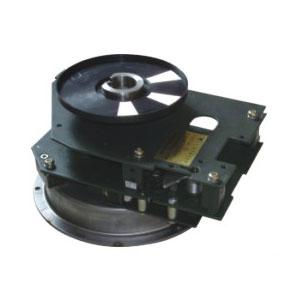
Our FLN38 series gas insulated load break switch adopts arc chute structure, which enables quick and reliable arc quenching. The interrupter switch is available in FLN38 series (K-type single-spring operating mechanism) and FLRN38 series (A-type single-spring operating mechanism). The FLRN38 type can be combined into a load break switch + fuse unit, which has control and protection functions.
Service Conditions
1. Ambient temperature
Highest temperature: +40 ℃
Lowest temperature:-40 ℃
2. Humidity: maximum average relative humidity
Daily average: ≤ 95%
Monthly average: ≤ 90%
3. Seismic capacity: 8 degrees
4. Altitude: ≤ 2000 m
Technical Parameters
FLN38-12 SF6 Gas Insulated Load Break Switch| No. | Item | Unit | Value | |||
| FLN38 | FLRN38 | |||||
| 1 | Rated voltage | KV | 12 | |||
| 2 | Rated frequency | Hz | 50 | |||
| 3 | Rated current | A | 630 | 125 | ||
| 4 | Rated insulation level |
Lightning impulse withstand voltage (peak) | KV | 75 (phase-to-phase, phase to earth), 85 (fracture) |
||
| 1 min power frequency withstand voltage | KV | 42 (phase-to-phase, phase to earth), 48 (fracture) |
||||
| 5 | Auxiliary circuit 1min power frequency withstand voltage | V | 2000 | |||
| 6 | Rated short-time withstand current / duration (earthing switch included) |
kA/s | 25/2 | |||
| 7 | Rated peak withstand current |
Main switch, earthing switch | KA | 63 | 125 | |
| 8 | Rated short-circuit breaking current |
Main switch, earthing switch | A | 63 | 125 | |
| 9 | Rated breaking current | Rated active load breaking current | A | 630 | ||
| Rated closed circuit breaking current | A | 630 | ||||
| No-load transformer capacity | kVA | 1250 | ||||
| Cable charging current | A | 10 | ||||
| 10 | SF6 gas rated inflation pressure (20 ℃gauge pressure) |
MPa | 0.045 ± 0.005 | |||
| 11 | SF6 gas yearly leakage rate | per year | ≤1% | |||
| 12 | Mechanical life (load switch) | times | 5000 | |||
| Mechanical life (earthing switch) | times | 2000 | ||||
| 13 | Moisture | PPm | ≤ 150 | |||
| 14 | Pole-center distance | mm | 210 ±2 | |||
| 15 | Different period of three-phase closing | ms | ≤ 10 | |||
| 16 | Different period of three-phase opening | ms | ≤ 15 | |||
| 17 | Main circuit resistance | μ Ω | ≤ 65 | |||
| No. | Item | Unit | Value | ||
| FLN 38 | FLRN 38 | ||||
| 1 | Rated voltage | KV | 24 | ||
| 2 | Rated frequency | Hz | 50 | ||
| 3 | Rated current | A | 630 | 125 | |
| 4 | Rated insulation level |
Lightning impulse withstand voltage (peak) | KV | 145 (phase-to-phase, phase to earth), 125 (fracture) |
|
| 1 min power frequency withstand voltage | KV | 79 (phase-to-phase, phase to earth), 65 (fracture) |
|||
| 5 | Auxiliary circuit 1min power frequency withstand voltage | V | 2000 | ||
| 6 | Rated short-time withstand current / duration (earthing switch included) |
kA/s | 25/2 | ||
| 7 | Rated peak withstand current | KA | 63 | ||
| 8 | Rated short-circuit breaking current | A | 63 | ||
| 9 | Rated breaking current | Rated active load breaking current | A | 630 | |
| Rated closed circuit breaking current | A | 630 | |||
| No-load transformer capacity | kVA | 1250 | |||
| Cable charging current | A | 10 | |||
| 10 | SF6 gas rated inflation pressure (20 ℃gauge pressure) | MPA | 0.045 ± 0.005 | ||
| 11 | SF6 gas yearly leakage rate | per year | ≤1% | ||
| 12 | Breaking transfer current | A | / | 1700 | |
| 13 | Short-circuit breaking current | kA | / | 310 | |
| 14 | Mechanical life (load switch) | times | 5000 | ||
| Mechanical life (earthing switch) | times | 2000 | |||
| 15 | Pole-center distance | mm | 275 ±2 | ||
| 16 | Different period of three-phase closing | ms | ≤ 5 | ||
| 17 | Different period of three-phase opening | ms | ≤ 5 | ||
| 18 | Main circuit resistance | μ Ω | ≤ 65 | ||

Main switch function: manual and electrical opening and closing operations are both allowed. The closing is only allowed when the earthing switch is in open state.
Earthing switch function: the opening and closing operation can only be done manually. When the main switch is in closed state, the earthing switch is not available.
Auxiliary switch:
Closing position: 2 normally open -2 normally closed;
Opening position: 2 normally open -2 normally closed;
Grounding position: 2 normally open -2 normally closed.
Mechanism indication:
Main switch and earthing switch status indication (K-type operating mechanism)
Main switch and earthing switch status indication, blown fuse indication (A-type operating mechanism)
Shunt trip coil is for A type operating mechanism.
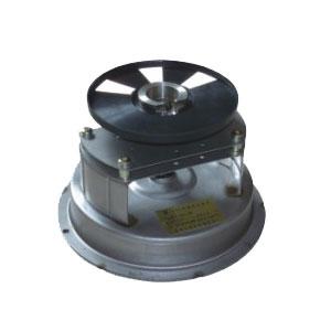
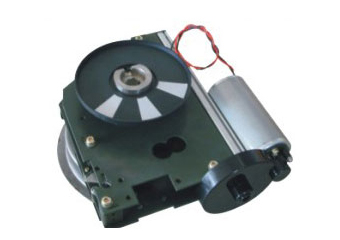
2. Electric operation: automatic opening and closing can be achieved through motor drive and control unit. The motor operating voltage can be AC220V, DC220V, DC48V, DC24V.

 English
 Español
 Русский