
Introduction
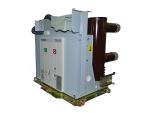
A circuit breaker (CB) is an electrical switch designed to protect electrical circuits from damage caused by overload or short circuit. Our TZN1 indoor vacuum circuit breaker (VCB) is the latest domestic achievement. It is available in many varieties, excellent in performance, and widely applicable to:
a. energy and infrastructure: power plants, 220KV/110KV substations, primary and secondary distribution systems.
b. industrial production: power supply systems for pulp and paper, construction materials (glass, cement, ceramics), steel and metal products, aluminum, petrochemical and other industrial productions.
c. building:power supply system of large-, medium-sized buildings and residential areas.
d. other: petrochemical, transportation, and mining areas


Complete Series
Rated voltage: 10kV (12kV), 20kV (24kV), 36kV (40.5kV)
Rated current: 630A, 1250A,1600A, 2000A, 2500A, 3150A,4000A,
Rated short circuit breaking current: 20kA, 25kA, 31.5kA, 40kA
Technology Leader
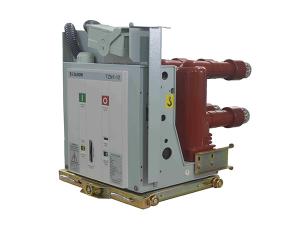
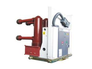
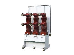
The use of the world latest embedded pole distinguishes the TZN1 indoor high voltage circuit breaker from others. The embedded pole is based on epoxy resin and cast by the most advanced APG technology. Vacuum interrupter, primary conductive circuit parts and isolated rod are enclosed together in the embedded pole to achieve a complete separation between the conductive circuit and the exterior. The structure is miniaturized and maintenance free, while having high dielectric strength, so as to allow the vacuum circuit breaker to run normally in harsh environment.
| Embedded pole: | Vacuum interrupter: | ||
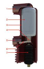 |
1. upper outlet 2. vacuum interrupter 3. epoxy resin 4. movable outlet rod 5. lower outlet 6. flexible connection 7. insulated rod |
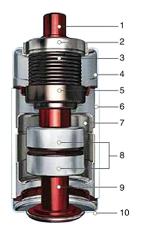 |
1. movable conductive rod 2. guide sleeve 3.bellow 4.movable cover plate 5. bellow shield 6. porcelain shell 7. shield tube 8.contact system 9. static conductive rod 10. static cover plate |
Flexible Configuration
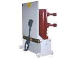
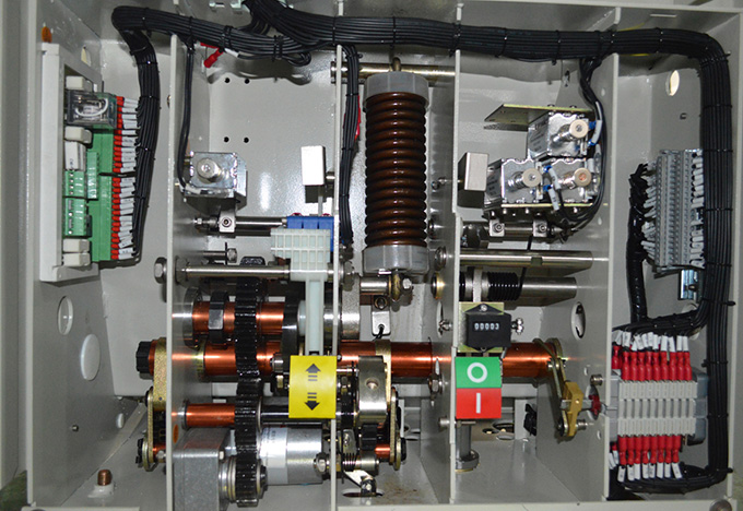
The operating mechanism of the TZN1 vacuum circuit breaker is of positive arrangement, allowing fixed and withdrawable mounting methods as well as manual and electric drive methods. The mechanism is suitable for ABB-UniGear, SIEMENS-NXAIR, SCHNEIDER-NVNEX and TELLHOW-KYN28A series medium voltage switchgears.
Superior Quality
TZN1 vacuum circuit breakers all should pass rigorous routine tests. Parts and their suppliers are required in accordance with the latest domestic supplier quality management system (SQM) to pass periodic assessment to ensure quality consistency. Our designing, manufacturing, mounting, and servicing comply with rules of ISO 9001: 2000 quality management system.
Environmentally Friendly
The design of the TZN1 vacuum circuit breaker is based on European environmental standards, in full compliance with requirements of ISO14001 environmental management system. Our waste parts recycling rate reaches as high as 80%.
| Rated voltage | Ur [kV] | 12 | 24 | 40.5 | |||||||
| Rated insulation voltage | Us [kV] | 12 | 24 | 40.5 | |||||||
| Frequency withstand voltage | Ud (1min)[kV] | 42 | 79 | 95 | |||||||
| Lightning impulse withstand voltage | Up [kV] | 75 | 145 | 185 | |||||||
| Rated frequency | Fr [Hz] | 50-60 | 50-60 | 50-60 | |||||||
| Rated current | Ir [A] | 630, 1250 | 630, 1250 | 630, 1250, 1600 2000, 2500, 3150 4000 |
1250, 1600, 2000 2500, 3150, 4000 |
630, 1250 | 630, 1250 | 630, 1250, 1600 2000, 2500,3150 |
630, 1250 | 630, 1250 | 630, 1250, 1600 2000, 2500,3150 |
| Rated breaking capacity |
Isc [kA] | 20 | 25 | 31.5 | 40 | 20 | 25 | 31.5 | 20 | 25 | 31.5 |
| Rated short time withstand current (4 seconds) |
Ik [kA] | 20 | 25 | 31.5 | 40 | 20 | 25 | 31.5 | 20 | 25 | 31.5 |
| Closing capacity |
Ip [kA] | 50 | 63 | 80 | 100 | 50 | 63 | 80 | 50 | 63 | 80 |
| Order of operations | [O-0.3s-CO-180s-CO] | ■ | ■ | ■ | ─ | ■ | ■ | ■ | ■ | ■ | ■ |
| [O-180s-CO-180s-CO] | ─ | ─ | ─ | ■ | ─ | ─ | ─ | ─ | ─ | ─ | |
| Opening time | [ms] | ≤ 50 | ≤ 50 | ≤ 50 | |||||||
| Arcing time | [ms] | ≤ 15 | ≤ 15 | ≤ 15 | |||||||
| Breaking time | [ms] | ≤ 70 | ≤ 70 | ≤ 70 | |||||||
| Closing operation rated voltage |
[V] | AC/DC 110/220/ 230/48/24 |
AC/DC 110/220/ 230/48/24 |
AC/DC 110/220/ 230/48/24 |
|||||||
| Opening operation rated voltage | [V] | AC/DC 110/220/ 230/48/24 |
AC/DC 110/220/ 230/48/24 |
AC/DC 110/220/ 230/48/24 |
|||||||
| Charging motor rated voltage | [V] | AC/DC 110/220/ 230/48/24 |
AC/DC 110/220/ 230/48/24 |
AC/DC 110/220/ 230/48/24 |
|||||||
| Charging motor rated power | [W] | 70 | 70, 120 | 70 | 70, 120 | 70 | 70, 120 | ||||
| Energy storage time | [s] | ≤ 15 | ≤ 15 | ≤ 15 | |||||||
| Mechanical life | [ times ] | 30,000 | 20,000 | 20,000 | 20,000 | ||||||
| Auxiliary switch |
NO+NC | 4NO+4NC, 7NO+7NC (Max.10NO+10NC) | 4NO+4NC, 7NO+7NC (Max.10NO+10NC) | 4NO+4NC, 7NO+7NC (Max.10NO+10NC) | |||||||
| Secondary circuit power frequency withstand voltage (1min) | [V] | 2,000 | 2,000 | 2,000 | |||||||
| Short circuit current breaking times | [ times ] | 274 | 274 | 274 | |||||||
| Rated short time current duration |
[s] | 4 | 4 | 4 | |||||||
| Breaker grading | [ms] | M2-E2-C2 | M2-E2-C2 | M2-E2-C2 | |||||||
| Switchgear Width (mm ) | 650 | 650 | 800 | 800 | 800 | 1000 | 1000 | 1000 | 1000 | 1000 |
| Rated current (A) | 630 | 1250 | 630 | 1250 | 1600 | 630 | 1250 | 1600 | 2000 | 2500-4000 |
| Rated short circuit breaking current (KA) |
20-31.5 | 20-31.5 | 25-31.5 | 25-40 | 31.5-40 | 25-31.5 | 25-40 | 31.5-40 | 31.5-40 | 31.5-40 |
| Pole-center distance (mm) | 150 | 150 | 210 | 210 | 210 | 275 | 275 | 275 | 275 | 275 |
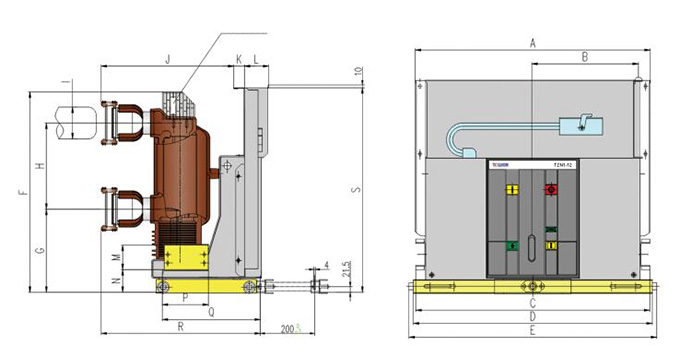
| A | 492 | 492 | 638 | 638 | 638 | 838 | 838 | 838 | 838 | 838 |
| B | 202 | 202 | 277 | 277 | 277 | 377 | 377 | 377 | 377 | 377 |
| C | 490 | 490 | 640 | 640 | 640 | 840 | 840 | 840 | 840 | 840 |
| D | 502 | 502 | 652 | 652 | 652 | 852 | 852 | 852 | 852 | 852 |
| E | 531 | 531 | 681 | 681 | 681 | 881 | 881 | 881 | 881 | 881 |
| F | 515 | 515 | 515 | 515 | 515 | 515 | 515 | 660 | 660 | 720 |
| G | 280 | 280 | 280 | 280 | 280 | 280 | 280 | 385 | 385 | 385 |
| H | 275 | 275 | 275 | 275 | 275 | 275 | 275 | 310 | 310 | 310 |
| I | Ф35 | Ф49 | Ф35 | Ф49 | Ф55 | Ф35 | Ф49 | Ф55 | Ф79 | Ф109 |
| J | 508 | 508 | 508 | 508 | 508 | 508 | 508 | 536 | 536 | 536 |
| K | 40 | 40 | 40 | 40 | 40 | 40 | 40 | 0 | 0 | 0 |
| L | 89 | 89 | 89 | 89 | 89 | 89 | 89 | 89 | 89 | 89 |
| M | 78 | 78 | 78 | 78 | 78 | 78 | 78 | 88 | 88 | 88 |
| N | 76 | 76 | 76 | 76 | 76 | 76 | 76 | 77 | 77 | 77 |
| P | 182 | 182 | 182 | 182 | 182 | 182 | 182 | 170 | 170 | 170 |
| Q | 433 | 433 | 433 | 433 | 433 | 433 | 433 | 361 | 361 | 361 |
| R | 598 | 598 | 598 | 598 | 598 | 598 | 598 | 586 | 586 | 586 |
| S | 637 | 637 | 637 | 637 | 637 | 637 | 637 | 698 | 698 | 735 |
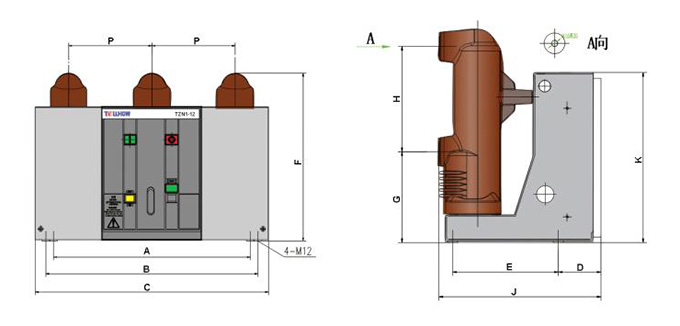
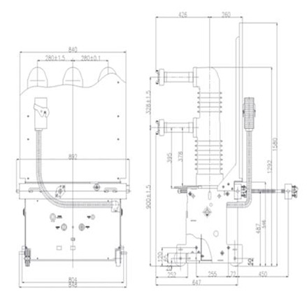
| Switchgear Width(mm) | Rated Current(A) | Rated short circuit breaking current(KA) | P | A | B | C | D | E | F | G | H | J | K |
| 650 | 630 | 25~31.5 | 150 | 400 | - | 453 | 111 | 275 | 557 | 237 | 205 | 422 | 445 |
| 650 | 1250 | 25~31.5 | 150 | 400 | - | 453 | 111 | 275 | 557 | 237 | 205 | 422 | 445 |
| 800 | 630 | 25~31.5 | 210 | 520 | - | 588 | 111 | 275 | 557 | 237 | 205 | 422 | 445 |
| 800 | 1250 | 25~31.5 | 210 | 520 | - | 588 | 111 | 275 | 557 | 237 | 205 | 422 | 445 |
| 800 | 630 | 25~31.5 | 210 | 650 | 700 | 770 | 111 | 275 | 557 | 237 | 275 | 432 | 445 |
| 800 | 1250 | 25~31.5 | 210 | 650 | 700 | 770 | 111 | 275 | 557 | 237 | 275 | 432 | 445 |
| 800 | 1600 | 31.5~40 | 210 | 650 | 700 | 770 | 111 | 275 | 557 | 237 | 275 | 432 | 445 |
| 1000 | 630 | 25~31.5 | 275 | 650 | 700 | 770 | 111 | 275 | 608 | 252 | 310 | 445 | 445 |
| 1000 | 1250 | 25~31.5 | 275 | 650 | 700 | 770 | 111 | 275 | 608 | 252 | 310 | 445 | 445 |
| 1000 | 1600 | 31.5~40 | 275 | 650 | 700 | 770 | 111 | 275 | 675 | 252 | 310 | 445 | 445 |
| 1000 | 2000 | 31.5~40 | 275 | 650 | 700 | 770 | 111 | 275 | 675 | 252 | 310 | 445 | 445 |
| 1000 | 2500 | 31.5~40 | 275 | 650 | 700 | 770 | 111 | 275 | 675 | 252 | 310 | 445 | 445 |
| 1000 | 3150 | 31.5~40 | 275 | 650 | 700 | 770 | 111 | 275 | 675 | 252 | 310 | 445 | 445 |
| 1000 | 4000 | 31.5~40 | 275 | 650 | 700 | 770 | 111 | 275 | 675 | 252 | 310 | 445 | 445 |
Note: when rated current reaches above 2500A, a cooler is required.
24kV Withdrawable Vacuum Circuit Breaker Dimensions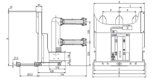
| Rated operating current (A) | Rated breaking current (KA) | Static contact size (mm) | Dimension data (mm) | ||||||
| 630 1250 |
25 31.5 | Ф 35 Ф 49 |
P | A | B | C | H | K | S |
| 210 | 638 | 652 | 640 | 770 | 681 | 277 | |||
| 275 | 838 | 852 | 840 | 815 | 881 | 377 | |||
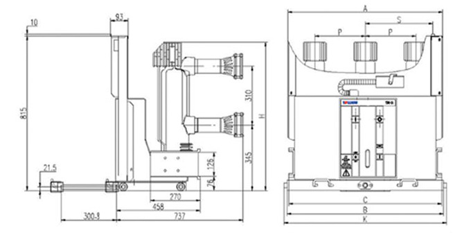
| Rated operating current (A) | Rated breaking current (KA) | Static contact size (mm) | Dimension data (mm) |
||||||
| 1600 2000 2500 3150 |
25 31.5 | Ф 55 Ф 79 Ф 109 Ф 109 |
P | A | B | C | H | K | S |
| 275 | 838 | 852 | 840 | 815 | 881 | 377 | |||
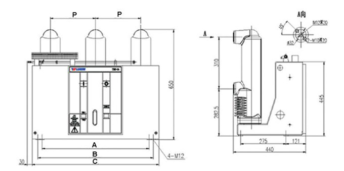
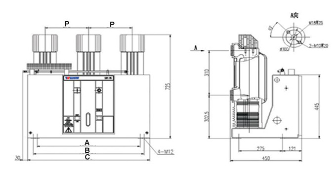
| Rated operating current (A) | Rated breaking current (KA) | Static contact size (mm) | Dimension data (mm) |
|||
| 630 1250 | 25 31.5 | - | P | A | B | C |
| 210 | 520 | - | 588 | |||
| 275 | 650 | 700 | 770 | |||
| Rated operating current (A) | Rated breaking current (KA) | Static contact size (mm) | Dimension data (mm) |
|||
| 1600 2000 2500 3150 |
25 31.5 | - | P | A | B | C |
| 275 | 650 | 700 | 770 | |||
| Rated operating current (A) | Rated breaking current (KA) | Static contact size (mm) |
| 1600 2000 2500 3150 |
25 31.5 | Ф 35 Ф 49 Ф 55 Ф 79 |

 |
 |
 |
 |
 |
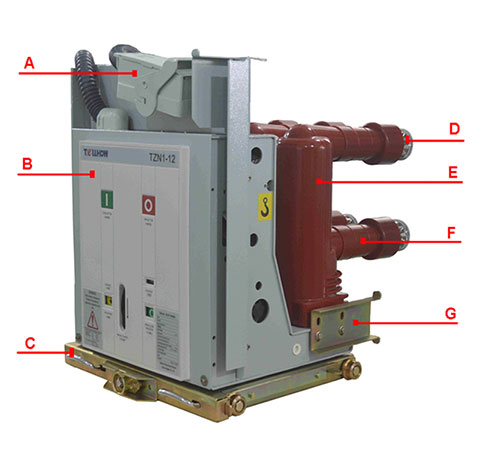
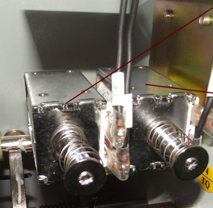
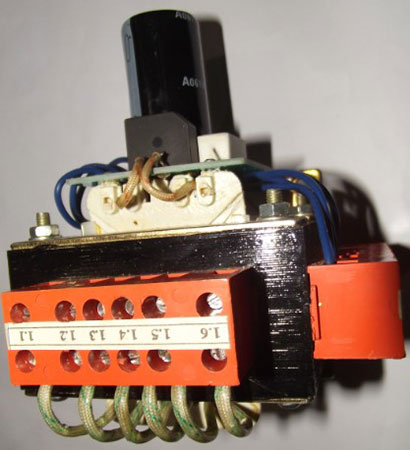
| Closing / Opening Coils TQ,HQ |
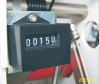
Counter |
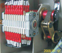
Auxiliary Switch QF |
Drive Device |
|
 |
 |
 |
 |
|
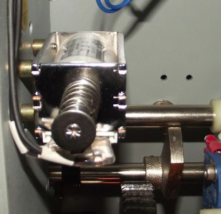
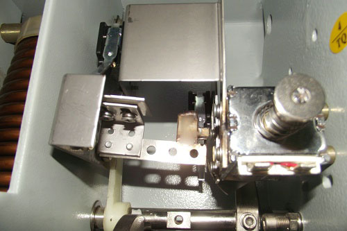
| Microswitch S1-S3 |
Charging Motor M1 |
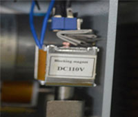
Electromagnetic Lock Y1 |
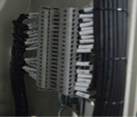
Terminal blocks for CB Truck |
PCB |
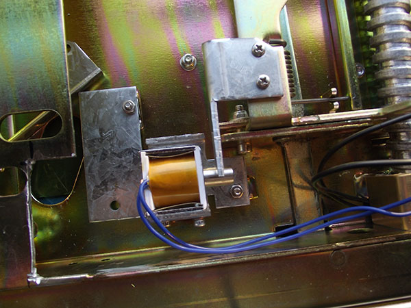
a. withdrawable latching solenoid (RL2)
The function is to prevent the withdrawable circuit breaker from being drawn into switchgear in the case of being connected with secondary circuit air outlet. For the secondary air outlet, matching proper pin matrix with different currents can prevent circuit breaker with wrong rated current from being drawn into switchgear.
b. secondary shunt opening release (MO2)
The opening release allows another set of independent secondary power supply, and allows remote opening control.
c. shunt opening release (MO1)
This allows remote opening control of the apparatus. The release can operate both in direct and alternating current.
d. opening solenoid (MO3)
The opening solenoid is a special demagnetization release, mounted on the right side of the mechanism, and the input control device is installed on the switchgear.
e. shunt closing release (TQ2)
The shunt closing release enables remote control over circuit breaker closing. AC and DC power supply are both workable for the operation. The continuous closing command applied to the closing release can achieve anti-skip function. This electrical characteristic is consistent with the performance of shunt opening release.
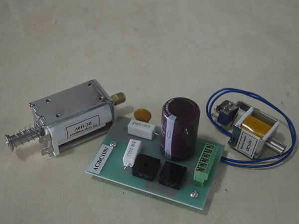
f. undervoltage and no-voltage device (MU)
When the secondary control power supply voltage falls below 65% or the power is off, the device will automatically opening the circuit breaker. The release cannot be used as spare opening release.
g. sliding contact (-S4)
Instantaneous sliding contact sends signals temporarily when the circuit breaker is opening. No signal is sent in the case of manual tripping, and mechanical interlock will act on the switches at two positions. In the case of electric opening, mechanical interlock usually acts on switches at frequent opening positions only.
| Service Conditions | |
| Normal service condition | indoor |
| Ambient temperature | -15 ℃ ~ + 40 ℃ |
| Altitude | *1000m |
| Humidity | |
| Daily average | ≤ 95% |
| Monthly average | ≤ 90% |
| Earthquake intensity | ≤ 8 grade |
For other requirements, please contact us.
| Standard Compliance | |
| IEC 62271-100 | High Voltage AC Circuit Breakers |
| IEC 60694 | Common Specification for High Voltage Switchgear and Control Gear Standards |
| GB1984-2003 | High Voltage AC Circuit Breakers |
| GB/T11022-1999 | Common Technical Requirements for HV Switchgear |
| DL/T 402-1999 | Technical Specification for HV AC Circuit Breaker |
| DL/T 403-2000 | Technical Specification for12kV- 40.5kV indoor HV AC Circuit Breaker |
| DL/T 593-2006 | Common Specification for HV Switchgear Enquiry and Orders |
| JB/T 3855-1996 | Technical Specification for 3.6kV- 40.5kV indoor HV AC Circuit Breaker |
Type Tests
a. dielectric strength test
b. temperature rise test
c. breaking capacity test
d. dynamic thermal stability test
e. mechanical life test
f. electrical life test
g. mechanical life curve
Special Tests
transport and storage test
Quality Control System
In the production process, each circuit breaker is manufactured with advanced processing technology and subjected to routine tests. This is to ensure good quality and consistency before delivery,in line with the requirements of ISO 9001:2000 quality management system. The test reports are signed by our quality control department to ensure the traceability.
The following items will go through our rigorous systematic routine tests:
a. 1 min power frequency withstand voltage test on main circuit: between open contacts, phase-to-phase, phase to earth
b. VCB mechanism operating low voltage test
c. dielectric test in auxiliary and control circuit
d. mechanical characteristic test
e. circuit resistance test
f. contact simultaneity test
g. opening and closing time
h. bouncing time
i. out-looking check
| TZN1 | 12 | 630 | 25 | 210 | D | |||
| Breaker name | Rated voltage | Rated operating current |
Rated short-circuit breaking current |
Pole-center distance | Breaker type | |||
| 12 | 12KV | 630 | 630A | 25 | 25KA | 150MM | D Withdrawable type | |
| 24 | 24KV | 1250 | 1250A | 31 | 31.5KA | 210MM | F Fixed type | |
| 40.5 | 40.5KV | 1600 | 1600A | 40 | 40KA | 275MM | K Floor type | |
| 2000 | 2000A | |||||||
| 2500 | 2500A | |||||||
| 3150 | 3150A | |||||||
| 4000 | 4000A | |||||||
 English
 Español
 Русский